


By Duane Benson, Chief Technology Champion, Screaming Circuits
As PCB assemblers, manufacturing is all about taking data from you and delivering good working circuit boards. Well, it can be just data — as in full turn-key, or data plus some parts, and PC boards — as in a partial turn-key or a kitted job. Regardless of whether you’re sending parts and boards, or having us buy everything, PCB assemblers need good data — and a lot of it.
 That data is the difference between the working boards you want and need, and a random jumble of expensive paperweights. We need a bill of materials (BOM), the job specifications which you give us by ordering and describing any special instructions, and the CAD design files. Fab and assembly drawings are always a good idea too. A little extra time spent on the files you send us leads to reduced risk — and that’s good for everyone.
The CAD design files include Gerbers, a Centroid (AKA pick and place or XYRLS file) and intelligent CAD files, such as ODB++ or IPC-2581. In some cases, such as EAGLECAD, we can use the native CAD board file.
The ODB++ and IPC-2581 file formats are the future of electronics manufacturing. They come with more data, and more accurate data than do Gerbers. If you can send either of these two, please do so. Even if you have those, you should still send the Gerber files. Gerbers are the lowest common denominator and provide a base that assemblers and PCB fab houses can work from.
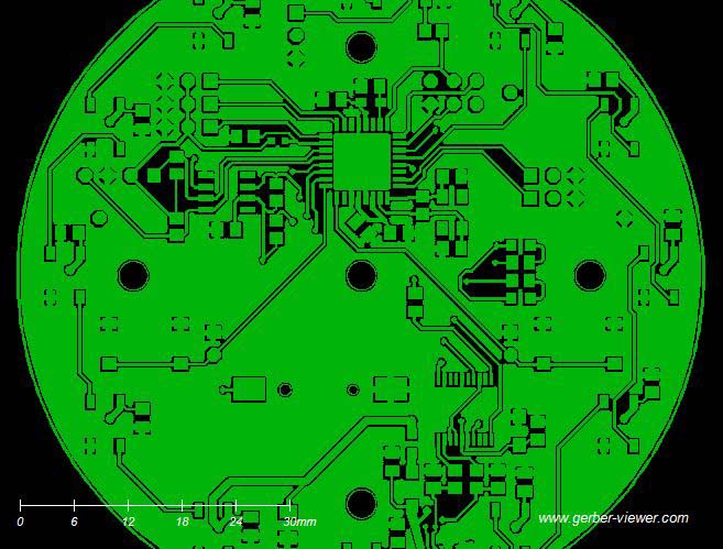
The Gerbers are a set of files used to create the various layers of the PC board. Each layer requires an individual file, so a six layer board (six copper layers) will typically require at least 13 distinct files:
- One for each copper layer
- Top solder mask
- Bottom solder mask
- Top silkscreen
- Bottom silkscreen
- The drills holes
- Solder paste for the top and bottom if the board has SMT parts on both sides
The drill file is combined with the gerbers to line up the via and thru-hole component holes with the appropriate spots in the PC board. Then the pick and place file will tell the assembly house where to put each component, what angle to place it at and which side of the board it goes in.
Fab drawings hold a human readable, often in PDF format, description of the board and any special instructions needed by the fab house. The assembly drawing would be the same, but for the assembly house.
Sometimes the parts are too densely packed for the reference designators and polarity marks to show up on the actual board, or for aesthetic reasons, the designer doesn’t want them on the board. In such cases, all of that information would be put into a set of assembly drawings — PDF files showing all of the necessary reference information.
The ODB++ and IPC-2581 file formats still aren’t universally accepted, but are getting more so all the time. Use and promotion of these new intelligent CAD output file formats help to reduce the number of manual steps and human interpretation, and will eventually lead to better quality and faster manufacturing times.
Duane Benson is the Chief Technology Champion at Screaming Circuits, a prototype PCB assembly electronic manufacturing company in Canby, Oregon