


By Patrick McGoff, Market Development Manager, Mentor-A Siemens Business
This year we celebrate the 55th anniversary of the introduction of the Gerber machine-language format. We can thank the man who took manual PCB design to the next level with the automated photoplotter for giving us the format in 1964.
America was still in shock from the assassination of John Kennedy. The Beatles toured America, riding on the popularity of their number one hit single, “I Want to Hold Your Hand.” Gasoline was 21 cents per gallon. Mary Poppins (the original) was playing in theaters. Cassius Clay defeated Sonny Liston to become the heavyweight champion of the world. The first Ford Mustang was introduced at a suggested retail price of $2,368.
And, Gerber Scientific Instrument Company introduced the Gerber format.
A History of Venerable Industrial Achievements
Joseph Gerber immigrated to the United States in 1940 with his mother following the death of his father during the Holocaust. Gerber started Gerber Scientific Instrument Company in 1948 to commercialize his first patented invention, the variable scale. He applied his aeronautical engineering degree to developing various solutions for industrial manufacturers.

Joe Gerber with the first product he invented and sold: the variable scale. (Photo courtesy of the Smithsonian.)
One of Gerber’s earliest products was a large-area plotter. These were used in the automotive and aerospace industries to plot digitized body components at full scale.
To make it easy for the early CAD tools to drive his plotters, Gerber decided to use a numerical control (NC) programming language developed a few years earlier at MIT Servomechanisms Laboratory. Ownership of this NC language was transferred to the Electronics Industry Association (EIA) and became known as EIA-RS274D. This is the same format that the metalworking industry used for two-axis milling.
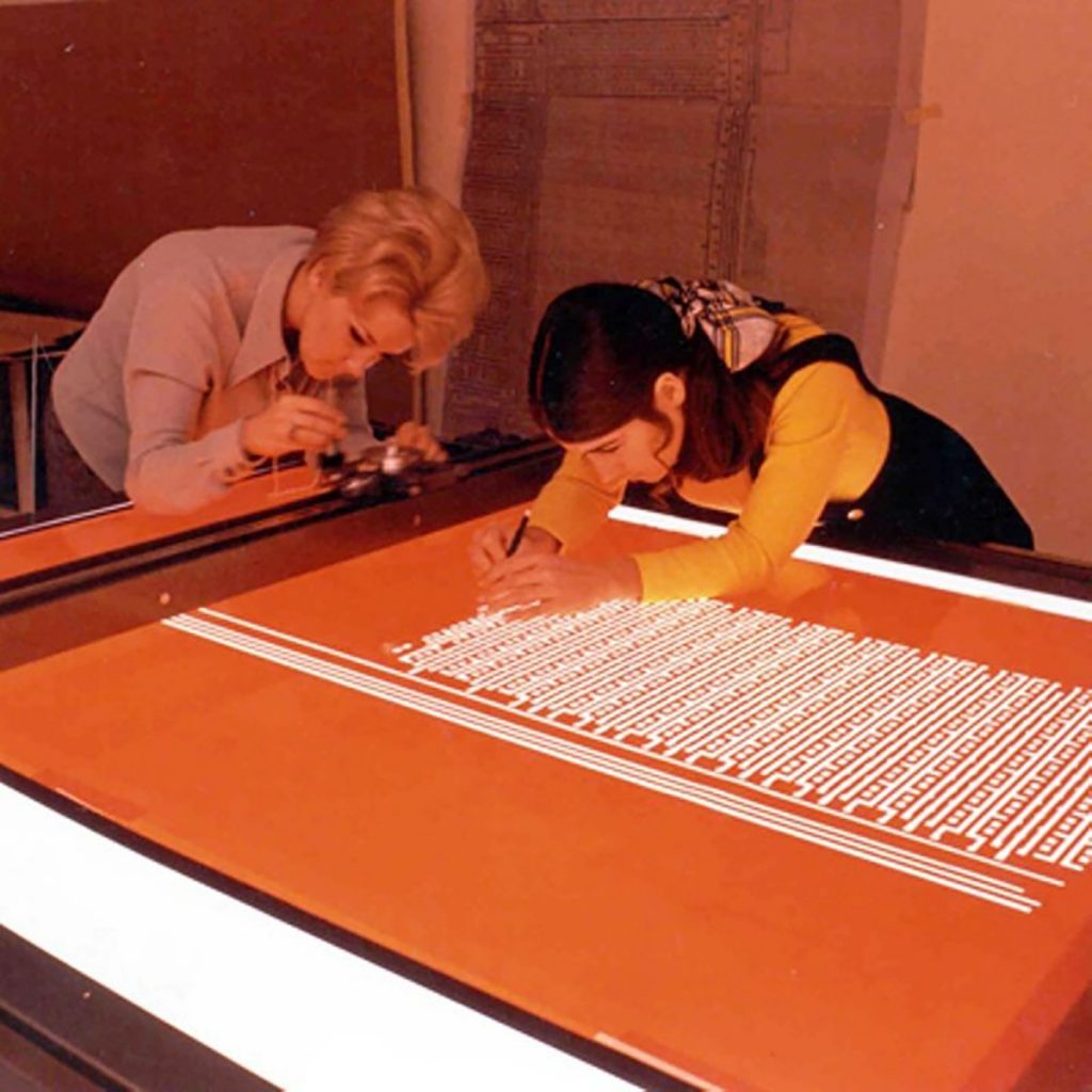
In 1967, the Radio Corporation of America (RCA) in Camden, New Jersey, asked Gerber to develop an automated rubylith cutting machine for their nascent printed circuit board (PCB) application. For those of you not familiar with the design-to-manufacturing process for PCBs at that time, rubylith was a thick film with a red peelable layer. Design departments used X-ACTO knives to cut the PCB pattern at a 20:1 scale. Then, the rubylith films were mounted on a large-format camera frame for photo-reduction to nominal size. The photo-reduction process reduced the mechanical tolerances of the cutting process.

Cutting rubylith film by hand. (Photo courtesy of the Computer History Museum and Intel.)
Gerber asked the engineers at RCA about their end-objective and realized that, if he imaged directly on the film, the customer could bypass intermediate steps while improving quality. With RCA’s support, the photoplotter was born. There’s a lesson here. Sometimes it makes more sense to understand and start with the ultimate desired result rather than starting with the focus on just automating a single step in the process—look at the whole forest, not just each tree alone.
Gerber created a derivative of the original format to suit his automated plotters. For example, the “T” codes in Gerber format represented tool (pen, and later, aperture) changes and the “G” codes for linear and circular motion were adopted, but certain miscellaneous (“M”) codes such as M08 for “coolant flood on” were excluded for obvious reasons.
The new photoplotters used a lamp in the photohead to project light through apertures of various sizes mechanically mounted on an aperture wheel to achieve the desired feature sizes on film. Back in the 1960s, 24 apertures pretty much covered all the features sizes and types you needed to design a PCB. Each aperture was sized for the circuit feature sizes of the time: 8, 10, 12, 15 and 20 mil round, complemented by special apertures for fiducials and thermal reliefs.

Gerber photoplotter and its controller. (Photo courtesy of the Smithsonian.)
For 20 years, designers at OEMs created their 1:1 photoplots on Gerber vector photoplotters and sent them as the master tool to their bareboard supplier. With the advent of laser photoplotters in the mid-1980s, the PCB fabricators added in-house photoplotting as a service and began asking for data instead of film.
What data format do you think they used? Correct—the Gerber format. After all, designers were already able to produce it and the new laser photoplotters accepted it. So Gerber became a data exchange format between designers and fabricators, along with Excellon drill files.
Then in 1991, in an effort to incorporate more aspects of the imaging process into the automated systems, two people—Ed O’Reilly of Gerber Scientific and Randy Allen of AT&T in Richmond, Virginia—collaborated in the development of an extended version of the Gerber format, called 274X. The 274X format allowed the inclusion of mass parameters such as layer polarity and aperture definitions within the plot file, thus eliminating what used to be known as the Gerber wheel file. It is interesting to note Gerber 274X never became an EIA standard. As the Gerber format already had become the de-facto standard, the industry simply accepted this new format as an improvement over the old one. Gerber 274X is still today the most widely used data exchange format in our industry.
But let’s now try to apply Gerber’s innovative way of looking at things. In the 1960s, we can speculate that he probably asked himself: What is it that electronics companies are trying to achieve? Aren’t we all trying to get our products to market as quickly as possible at the lowest possible cost and at a defined quality level? And today, he might ask: Is using a format derived from 55-year old technology the best way to remain competitive in the marketplace?
Can you name a single other data format, or its derivative, that is still in widespread use 55 years after its introduction? I couldn’t think of one either.
That says a lot for the Gerber format’s usefulness. But with every PCB design you receive from your customers in the form of legacy CAM data such as Gerber, you are putting your company’s objectives at risk. You are not simply getting Gerber files, you are also getting netlist files, test files, BOM data, centroid data, documentation files, drawings, and instructions. You can’t assume that all of the files sent in data delivery package are compatible. Many times they don’t even come from the same system. So, in an attempt to minimize the risk of dealing with conflicting information, your team is spending resources validating these various files.
The attributes and properties that are inherent in all EDA data get lost when exported to unintelligent formats like Gerber. Because of that, you are spending unnecessary time to reverse engineer the PCB model before you can perform your value-added services. Not only is that inefficient, it is also susceptible to error. How often do you as a contract manufacturer have to tell your customer their job is on hold because of a question about the data package? How often are they happy about that delay?
Why do we continue to limit our competitiveness as an industry by relying on old methodology? I know we don’t like to say no to a customer, but to be competitive in today’s market, the entire supply chain needs to commit to efficiency, beginning with the data.
The issue of materials costs has been milked as much as it can. Contract manufacturers are asked to make perfect PCBs that are each a custom product but at a commodity price; they then get dumped with dumb data sets and are told to “deal with it,” or “the other shop didn’t have a problem with the data.” What do you think the results would be if, instead, we could get the contract manufacturers treated as a critical supply-chain partner and asked them what could be done to improve the product’s quality and costs and accelerate the time to market? What do you suppose they would say? Probably not to keep doing things the way they have always been done.
The Next Generation
Since 1995, the ODB++ data exchange format has offered the PCB industry an alternative that enables creation of intelligent product models (and to be fair, it’s now nearly a quarter century old). Like its predecessor, ODB++ was not originally developed with the intent of becoming a data exchange standard. Rather, it was the database format for Valor’s Genesis CAM software used by the PCB fabrication industry. As OEMs and contract manufacturers also began adopting the Valor DFM solutions, the forwarding-thinking electronics companies of the time saw an opportunity to strengthen and improve their supply-chain partnerships using ODB++.
ODB++ caught on because it was comprehensive: it allowed building a single product model that included all the necessary fabrication, assembly, and test data needed to manufacture a PCB. This product model contains layer definitions, polarity, netlist, component layers, and test points all clearly and consistently attributed so that all users of the data could benefit from the information as the product moved from design to fabrication, assembly, test, and manufacturing. It replaces several formats using one deliverable. The specification has evolved and remains free to everyone as does the ODB++ Viewer.

Benefits of using a single product model containing all the necessary data to build a PCB.
In a recent global study conducted by Mentor, 48.7% of all companies responding said they use ODB++ for at least one of their functions (fabrication, assembly, test, DFM, or viewing). Certainly, the industry gravitates to solutions that are practical and proven.
What Will the Future Look Like?
As electronics technology and manufacturing moves deeper into the digital age, what will the machines, tools, and data look like? How will it change and what will we need to do to adapt? New questions would probably be asked by Gerber at this juncture—we need to be asking them ourselves to continue to compete and innovate as the world changes.
The truth is, as advanced as the electronics industry is, some companies are still holding on to the legacy Gerber format. It served its time well, but we currently have a more-efficient data exchange format to take us to the next level. At 48.7% ODB++ usage, critical mass has been reached—the tipping point achieved. Now it’s time for the next level.
I do not know of a single contract manufacturer that cannot take in ODB++ data today. What if, as a contract manufacturer, in addition to stating to your customers the flexibility you have in taking in various data sets, you also stated which data format your engineering department prefers? You could even arm your sales team with a single slide as to why you prefer an intelligent, comprehensive data format such as ODB++. That one slide would likely save your engineering department hundreds of hours every year.
Gerber listened to his customer: rather than just trying to automate a single step in the process, he addressed RCA’s end goal. When laser plotters were invented in the 1980s, the machine makers continued to use the Gerber format, and so it became the de facto data-exchange format. As we celebrate this achievement, let’s look at where we can go today, after more than half a century.
We are all still trying to get products to market as quickly as possible at the lowest possible cost and at a defined quality level, but in a world of technology that has changed drastically in the last 20 years, in the last 10 even more, and is continuing to be in flux in an increasingly uncertain global market. Gerber would probably agree that with today’s rapidly changing market demands and sophisticated technology, an evolving comprehensive digitalized format is better for continuing innovation.